
Technical Notes
Why In-Spec CNC Machined Parts Can Still Fail During Assembly
A CNC machined component can pass inspection, appear fully within tolerance, and still create problems during assembly.
This is one of the most common misunderstandings in precision machining. A quality report may confirm that individual dimensions were checked, but assembly performance depends on how those features work together. A shaft diameter, bore size, shoulder distance, thread, cross hole or surface finish can each meet its own requirement while the finished part still does not seat, align, rotate, seal or fasten correctly.
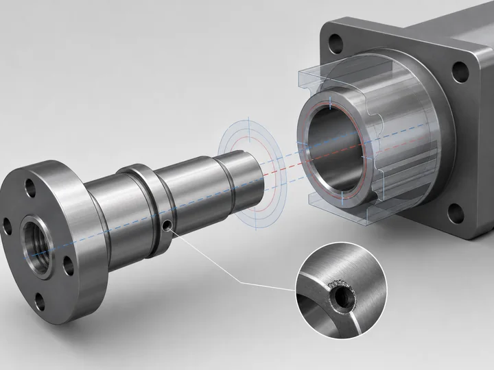
Individual Dimensions Do Not Always Reflect Assembly Function
CNC machining inspection often checks individual features such as:
- Outside diameters
- Bore diameters
- Hole size
- Shoulder distance
- Thread size
- Surface finish
- Overall length
These checks are necessary, but assembly does not evaluate each feature in isolation. Assembly depends on relationships between features and mating parts.
For example, a turned shaft may have correct diameters, but if the locating shoulder, threaded end and functional OD are not controlled from the right datum, the shaft may not align correctly in the final assembly. A sleeve may have an in-tolerance bore and OD, but if the bore-to-OD relationship is not controlled, the part may not locate as intended.
This is why the drawing should make the functional relationships clear, especially for parts used in automation equipment, motion components, valve assemblies, fittings and other mechanical systems.
Datum Relationships Can Create Hidden Risk
Datum selection affects how a part is machined, measured and understood. If the drawing does not clearly identify the functional datum, the part may be inspected from a surface that is easy to measure but not important to the assembly.
Common examples include:
- A shoulder located from a non-functional end face.
- A cross hole positioned from an edge that is not used during assembly.
- A bore and OD inspected separately when they should be related.
- A thread that passes gauge inspection but is not aligned with the locating diameter.
- A face that meets length tolerance but is not controlled relative to the axis of rotation.
When the assembly depends on a specific datum, that datum should be visible in the drawing and discussed during RFQ review.
Tolerance Stack-Up Can Cause Assembly Interference
Even when each part is within tolerance, variation can accumulate across multiple interfaces. This is called tolerance stack-up.
In CNC machined assemblies, stack-up problems often appear around:
- Shaft and bore fits
- Bearing seats
- Shoulder-to-shoulder distances
- Thread engagement lengths
- Groove and seal positions
- Spacer and sleeve lengths
- Mating faces and stops
The issue is not always that one part was machined incorrectly. Sometimes the tolerance range allows a combination of parts that is technically acceptable on paper but difficult in assembly.
Tightening every tolerance is not always the best solution. A better first step is to identify which features are truly critical to function and how they interact with mating parts.
Runout and Coaxiality Matter for Shafts and Rotating Parts
For turned parts, diameter size is only one part of the problem. The relationship between axes can be more important than the size of a single feature.
A shaft can have all diameters within tolerance and still create assembly or performance issues if runout or coaxiality is not controlled where it matters. This is especially important for parts that rotate, locate bearings, carry sleeves, connect to couplings or guide motion.
Typical risk areas include:
- Multiple OD sections that must share a functional axis.
- A bore that must remain aligned with an outside diameter.
- A threaded end that must be coaxial with a locating diameter.
- A shoulder face that must be square to the rotating axis.
- A milled flat or cross hole that must align to a turned feature.
If runout or coaxiality affects function, the drawing should define the requirement clearly rather than relying only on diameter tolerances.
Bore-to-OD Relationship Can Be More Important Than Bore Size Alone
Sleeves, bushings, spacers, adapters and similar turned components often depend on the relationship between the internal bore and external diameter.
The bore may pass size inspection. The OD may also pass size inspection. But if the bore is not sufficiently aligned with the OD, the part may create uneven contact, assembly misalignment, poor rotation, sealing issues or inconsistent wall thickness.
Buyers should pay attention to bore-to-OD relationships when the part:
- Locates on the OD while another part passes through the bore.
- Presses into a housing.
- Supports a shaft or pin.
- Forms part of a sealing or flow path.
- Requires even wall thickness for strength or assembly stability.
When this relationship matters, it should be controlled and inspected as a functional requirement.
Hole Position and Cross-Hole Alignment Can Affect Fit and Flow
Turn-mill parts often include cross holes, radial holes, ports, flats, slots and threaded features. These features can be correct individually but still cause problems if their position or angular relationship is not controlled.
Important details include:
- Cross-hole location relative to a shoulder or end face.
- Angular position relative to a flat, slot or second hole.
- Hole breakthrough into a bore, groove or passage.
- Distance from the hole edge to a thin wall.
- Burr control around intersecting holes.
- Alignment between drilled, milled and turned features.
This is especially important for shaft parts, adapters, fittings and components with flow passages or fastening features. A hole that is the right size but in the wrong functional position can still prevent proper assembly.
Burrs and Edge Conditions Can Stop Assembly
Burrs are small, but they can cause serious assembly problems. A part may pass dimensional inspection while a burr remains on a cross hole, thread start, bore entrance, slot edge or shoulder.
Burrs can cause:
- Difficult insertion.
- Scratching on mating parts.
- Thread starting problems.
- Poor seating against a shoulder.
- Flow restriction in small passages.
- Seal damage.
- Inconsistent fit during assembly.
General deburring notes are useful, but they may not be enough for burr-sensitive components. If a specific edge is critical, the drawing should identify it clearly.
For example, cross holes intersecting a bore usually need more attention than a non-functional outside edge. Thread starts, internal grooves and sealing edges may also need specific review before production.
Thread Fit Can Be Correct but Still Not Work in Assembly
Thread inspection usually confirms that the thread meets a defined standard or gauge requirement. But thread function can still be affected by surrounding features and secondary processes.
Common risks include:
- Thread depth or engagement length not matching the mating part.
- Burrs at the thread start or thread exit.
- Plating, anodizing or coating changing thread fit.
- Thread axis misalignment with a locating diameter.
- Missing relief near the end of the thread.
- Incomplete cleaning after machining.
If the thread is used for sealing, adjustment, load transfer or precise positioning, it should be reviewed together with the full assembly condition.
Surface Treatment Can Change the Final Part
Surface treatment can affect the final fit of a CNC machined component. Processes such as anodizing, plating, black oxide, passivation or other finishing operations may influence dimensions, thread fit, bore fit, surface roughness and edge condition.
Buyers should clarify whether critical dimensions apply before or after surface treatment. This is especially important when:
- A bore or OD has a close fit.
- Threads must assemble smoothly after finishing.
- A sealing surface is treated.
- A part requires both cosmetic and functional finishing.
- Coating thickness may affect mating features.
If finishing is part of the final requirement, it should be included in the RFQ package and drawing notes.
Inspection Reports Do Not Always Confirm Function
Inspection reports are important, but they do not automatically prove that a part will work in assembly.
Standard inspection may confirm:
- Individual dimensions.
- Thread size.
- Hole diameter.
- Surface finish.
- Material or finish requirements where specified.
But assembly may depend on:
- Feature relationships.
- Datum-based measurement.
- Runout and coaxiality.
- Burr condition.
- Contact under tightening or load.
- Fit after surface treatment.
- Relationship between the machined part and mating components.
For critical components, the inspection method should match the functional requirement. If the part must locate from a specific bore, shoulder or OD, that relationship should be reflected in the inspection plan.
Buyer Drawing Checklist
Before sending a CNC machining RFQ, buyers can review the drawing with the following questions:
- Which features are critical to assembly function?
- Are the functional datums clearly defined?
- Are runout, coaxiality or perpendicularity requirements needed?
- Does the bore-to-OD relationship matter?
- Are hole positions controlled from the correct datum?
- Are angular relationships between holes, flats, slots or threads clear?
- Are shoulder distances, relief grooves and corner radii suitable for the mating part?
- Are burr-sensitive edges identified?
- Are thread class, thread depth and thread finish requirements clear?
- Do critical dimensions apply before or after surface treatment?
- Are inspection requirements stated for critical features?
- Is the 3D model consistent with the 2D drawing?
This checklist does not replace the buyer's engineering review, but it helps reduce assumptions before quotation and production.
Inspection Focus for Assembly-Critical CNC Parts
For parts where assembly depends on feature relationships, inspection should go beyond simple size checks.
Useful inspection focus areas may include:
- Datum-based measurement of critical dimensions.
- Runout checks for shaft and rotating features.
- Coaxiality or concentricity review where required by the drawing.
- Bore-to-OD relationship for sleeves, bushings and adapters.
- Hole position relative to shoulders, ends, flats or other holes.
- Thread fit after machining and, where relevant, after surface treatment.
- Burr inspection around cross holes, thread starts and internal edges.
- Visual and dimensional review of shoulders, reliefs and seating faces.
The inspection approach should match how the part functions in the assembly.
How DXSCNC Reviews These Risks
DXSCNC reviews drawing-based CNC turned and turn-mill components by focusing on critical features, functional relationships and inspection requirements before production.
During RFQ review, DXSCNC can look for areas that may need clarification, including datum selection, feature relationships, thread requirements, burr-sensitive areas, material and finish notes, and inspection expectations. This helps reduce avoidable back-and-forth and supports a clearer quotation process.
Some assembly conditions can only be confirmed by the buyer's design team. But when the drawing clearly identifies functional features and critical requirements, the machining review can be more practical and focused.
Related Links
- CNC Turning
- Turn-Mill Machining
- CNC Machined Shafts
- Machined Sleeves and Bushings
- Threaded Components
- Adapters and Fittings
- Quality Inspection
Request a Quote
If you have a drawing-based CNC turned or turn-mill component with critical assembly requirements, send the drawing, material, quantity, finish requirements and inspection notes to DXSCNC for review.
FAQ
Can a CNC machined part pass inspection and still fail assembly?
Yes. A CNC machined part can meet individual dimensional tolerances but still fail assembly if important relationships between features are not controlled, inspected or understood in the same way the part functions.
What does "in spec" mean in CNC machining?
"In spec" usually means the measured dimensions or requirements are within the tolerances shown on the drawing. It does not always confirm that the part will work correctly in the final assembly.
Why can tolerance stack-up cause assembly failure?
Tolerance stack-up happens when small variations across several parts or features combine. Each dimension may be acceptable by itself, but the combined condition may create interference, looseness, misalignment or poor seating.
Why are datum relationships important for CNC machined parts?
Datum relationships define how features are located and measured relative to each other. If the wrong datum is used, a part may pass inspection but still not match the way it is located in the final assembly.
How can buyers reduce the risk of assembly problems?
Buyers can reduce risk by marking critical features, defining functional datums, clarifying runout or coaxiality requirements, identifying burr-sensitive areas, confirming thread and finish requirements, and sharing assembly-related notes during RFQ review.